
Module 4
Under Part 107, for design and operation, the requirements (or constraints) are more about safe flight operation rather than structural certification. Key points:
The drone must be registered; operators must place the issued registration number visibly on the aircraft.
Operational limitations: typically within visual line-of-sight (VLOS), daylight (or twilight with proper lighting), max altitude ~400 ft above ground (or above structure under certain conditions), max speed ~100 mph (87 knots).
Pre-flight safety checks: the operator is responsible for ensuring the drone is safe to fly (communications link, control surfaces, etc.).
- DGCA / FAA category compliance
- BVLOS / VLOS operational constraints
- Weight class limits
Key questions to consider include:
a) Does the product meet the customer’s actual needs?
b) What is the estimated market size—how many units can be sold?
c) Will the production cost plus mark-up be perceived by customers as good value for money?
d) Are the projected operating costs and system reliability acceptable to customers?
e) Can the programme’s non-recurring costs be recovered within a reasonable timeframe through sales revenue?
f) Are there any political, regulatory, or external factors that may restrict the sale of the aircraft or system?
Stepwise procedure includes:
1. Expand the initial UAV system outline into detailed configurations, performing optimisation trade-offs to ensure maximum performance across expected missions and environmental conditions.
2. Identify which UAV components will be built in-house and which will be externally sourced, along with approximate procurement costs and supplier options.
3. Finalise a complete system design definition, including subsystem interfaces and a full UAV system specification for further development.
4. Reassess programme costs for upcoming development phases and operational expenses to confirm whether continuation of the UAV project is justified.
5. Avoid rushing this phase, as careful early consideration of manufacturability, reliability, maintenance, and operational aspects prevents costly corrections in later UAV development stages.
Stepwise procedure includes:
1. Detailed studies of UAV aerodynamics, dynamics, structures, and onboard systems are carried out, along with layouts for control stations and support subsystems.
2. Designers create production-ready drawings for all UAV components, including ground support and test equipment, while applying value analysis to optimize cost and performance.
3. Specifications for externally purchased components are finalized, and tenders are invited from suitable suppliers for procurement.
4. Required manufacturing jigs and tools are identified and designed unless sourced externally to ensure accurate UAV production.
5. Test schedules for upcoming evaluation phases are drafted, and initial content for UAV operating and maintenance manuals is prepared.
1. Mission-Oriented Design
2. Keep Weight Low
3. Optimize Aerodynamics
4. Ensure Stability & Control
5. Use Efficient Propulsion
6. Ensure Structural Integrity
7. Choose Reliable Avionics
8. Add failsafe settings
CFD, XFOIL, AVL, MATLAB performance iteration.
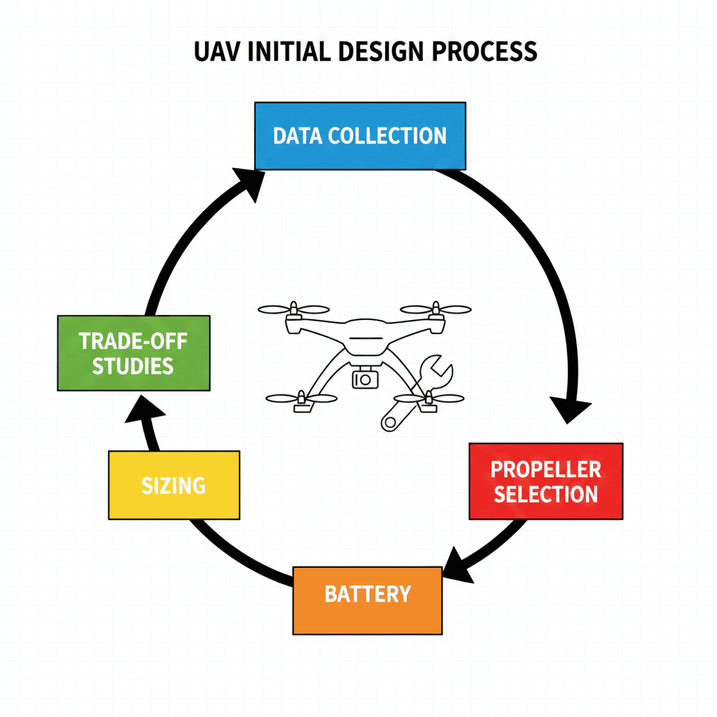
Initial Design Process
Data Collection: This is the foundational step. It involves defining the mission requirements (e.g., payload, flight duration, range, operating environment, size constraints) and gathering component data (e.g., motor specifications, battery energy density, propeller performance curves) that will drive all subsequent decisions.
Trade-Off Studies: This step evaluates different combinations of design parameters to find the optimal configuration. It often involves analyzing the impact of factors like increasing battery weight (more energy, less payload capacity) versus reducing flight duration (less battery weight, more payload capacity) to balance competing objectives.
Sizing: Based on the trade-off studies, this step determines the preliminary size and weight of the overall aircraft and its key subsystems. It sets the required thrust-to-weight ratio and estimates the total takeoff weight needed to meet the defined mission.
- Type of mission: Surveillance, mapping, delivery, agriculture, etc.
- Operational range (Rreq)
- Endurance (treq)
- Cruise speed (Vc)
- Ceiling / Operating altitude
- Payload mass (Wpl) in (kg)
- Launch & recovery constraints (Runway, VTOL, catapult)
Payload Requirements based on Payload mass (mpl),Payload type (Camera, sensor, sprayer, communication module), and Power requirement for payload (Ppl).
Initial Maximum Takeoff Weight (MTOW):
WTO = g × (mpl + mbatt/fuel + mstruct + mavionics)
WTO (or, MTOW) = (Wpl + Wbatt/fuel + Wstruct + Wavionics)
- For the initial design, we select a maximum stall speed (Vstall) constraint of 12 to 15 m/s, which is typical for a small UAV, and we target a maximum lift coefficient (CLmax) in the range of 1.2 to 1.6 to ensure adequate low-speed performance and lift capability.
- Wing loading: W/S = WTO / S
- Cruise lift coefficient: CL,c = (2WTO) / (ρ Vc2 S)
- Stall speed: Vs = √[2WTO / (ρ S CL,max)]
- For small-to-medium fixed-wing UAVs, the typical operational ranges are:Low-to-Moderate AR: Commonly in the range of 2 ≤ AR ≤ 7 for man-portable or hand-launched small tactical UAVs.
- Medium-Velocity AR: Often around 8 ≤ AR ≤ 15 for conventional, medium-velocity UAVs.
- Glider/High-Endurance AR: Typically AR > 15.
If wing-based uav, determine wing area (S).
The selection of AR is a primary trade-off study because it directly impacts performance, where Aspect ratio, AR = b2/S
- Material selection (Carbon fiber, composites, aluminum)
- Safety factor: 1.5 – 2.0
- Wing root bending moment estimates:
Mroot ≈ q × (b/2)2 / 2
- Required thrust: Treq ≈ D
- Mathematically, Treq=(T/W)×WTO
- Drag coefficient: CD = CD0 + (CL2 / (π AR e))
- Power Required from T/W,Using actuator disk theory. Power required: P = Drag Force × Vc
- Hover power Estimation: number of motor * Per motor power.
- Electric power input: Pelec = P / ηp
The Thrust-to-Weight ratio (T/W) is a critical metric used to ensure the UAV can perform its required maneuvers.Any VTOL (Vertical Take-Off and Landing) UAV must have a T/W of at least 1.0 to simply hover and overcome gravity.To ensure safe and rapid ascent, VTOL designs often select a much higher T/W margin, typically between 1.8 and 2.5, for takeoff.
or, P = T3/2 / √(2ρA).Where Disk area per prop,A = πD²/4, . Note that increasing the T/W ratio leads to an exponential increase in power consumption, directly impacting battery sizing.
These calculations determine the required energy capacity and resulting mass of the battery, which is crucial for closing the design loop and verifying the initial weight estimates.
- Total Energy Required (Ereq): The base energy required for the mission (Ereq) is calculated from the average power draw and flight time: Ereq = Pavg × t
- Battery Energy Capacity (Ebat): A safety reserve of 20–30% is added to determine the actual battery capacity needed: Ebat = 1.25 × Ereq
(Using a 25% reserve factor for robustness)
- Battery Capacity CAh):Capacity in Ampere-hours is calculated considering the battery voltage (Vbat) and system efficiency (ηsys): CAh = Ebat / (Vbat × ηsys)
Note: System efficiency ηsys is typically assumed to be around 0.85 (85%).
Battery energy must satisfy:
Ebatt ≥ Pavg × treqIf using fuel (Breguet):
R = (ηp / cT) × (L/D) × ln(Wi / Wf) - Battery Mass Estimation (Wbat): The final, critical step is to estimate the mass of the battery pack, which heavily influences the overall UAV sizing and T/W ratio. This is determined by dividing the required energy by the selected battery's Energy Density Wbat = Ebat / Energy Density
| Battery Type | Typical Energy Density |
|---|---|
| Li-ion (Lithium-ion) | ~240 Wh/kg (Better for long endurance/range) |
| Li-Po (Lithium-Polymer) | ~200 Wh/kg (Better for high power/burst current) |
- Static margin: SM = (xac − xcg) / c̄
- Control authority based on mission maneuver requirements
where xac = aerodynamic center location, xcg = center of gravity, c̄ = mean aerodynamic chord. Typical static margin: 5–15% of c̄ (fixed-wing, stable).
| No | Component | Configuration Alternatives |
|---|---|---|
| 1 | Fuselage | – Geometry: lofting, cross section – Internal arrangement – Accommodation: payload, fuel, engine, landing gear |
| 2 | Wing | – Type: rectangular, swept, tapered, dihedral – Airfoil, twist angle, setting angle – Location: low-wing, mid-wing, high wing, parasol – High-lift devices: flap, slot, slat – Attachment: cantilever, strut-braced |
| 3 | Horizontal Tail | – Configuration: conventional, T-tail, H-tail, V-tail, inverted V – Type: rectangular, swept, tapered, dihedral – Airfoil, twist angle, setting angle – Installation: fixed, moving, adjustable – Location: aft tail, canard, three-surface |
| 4 | Vertical Tail | – Configuration: single, twin VT, V-tail – Type: rectangular, swept, tapered – Airfoil |
| 5 | Engine | – Type: turbofan, turbojet, turboprop, piston-prop, electric – Location: under fuselage, under wing, beside fuselage, fuselage nose, rear fuselage – Number of engines |
| 6 | Landing Gear | – Type: fixed, retractable, partially retractable – Configuration: tricycle, bicycle, tail gear, multi-bogey, no landing gear |
| 7 | Control Surfaces | Separate vs all-moving tail, reversible vs irreversible, Conventional vs non-conventional (e.g., elevon, ruddervator) |
| 8 | Autopilot | – UAV dynamic model: linear, nonlinear – Controller: PID, gain-scheduling, optimal, robust, adaptive, intelligent – Guidance subsystem: proportional navigation, line-of-sight, command guidance, three-point, lead, waypoint – Navigation subsystem: inertial navigation (strap-down, stable platform), GPS |
| 9 | Launch & Recovery | HTOL, ground launcher, net recovery, belly landing |
| UAV Weight | T/W | Typical Propeller Diameter |
|---|---|---|
| 1 kg | 2.0 | 9–11 in |
| 2 kg | 2.0 | 11–13 in |
| 5 kg | 2.0 | 15–17 in |
| 10 kg | 2.0 | 18–22 in |
| 5 kg (Fixed-Wing) | 0.4 | 10–12 in |
UAV Mission Classification Dashboard
UAV classification system to identify suitable UAV categories, wing configurations, recommended sensors, and approximate weight classes.
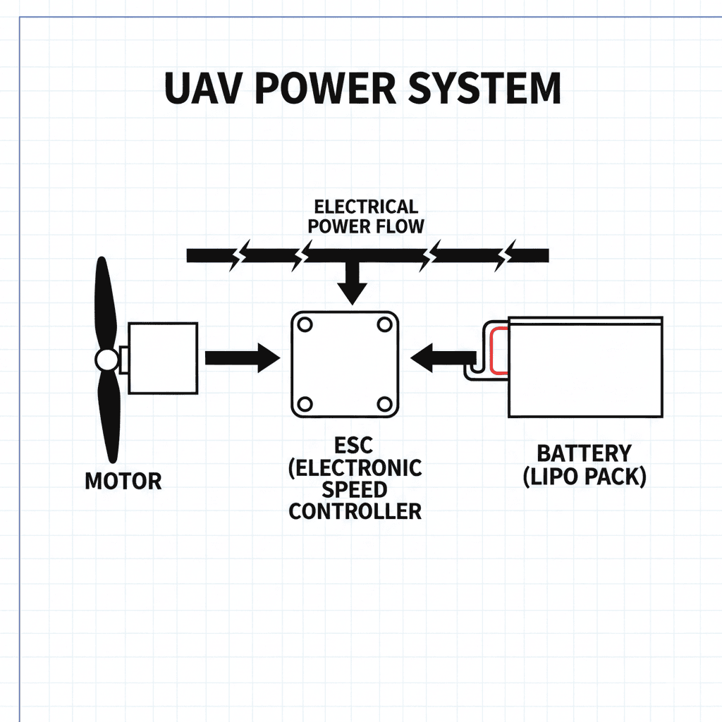
Motor–ESC–Battery Matching Table
| UAV Scale | Motor (KV) | ESC Rating | Battery (S) |
|---|---|---|---|
| Micro / Racing | 2300 – 2700 KV | 20A – 40A | 3S – 4S |
| Small / Photo | 900 – 1200 KV | 30A – 50A | 3S – 4S |
| Medium / Delivery | 500 – 800 KV | 40A – 60A | 4S – 6S |
| Heavy Industrial | 100 – 400 KV | 80A – 120A+ | 6S – 12S |
UAV Propulsion Calculator
UAV Propulsion Calculator
1.1 Pre‑Connection Checklistverify all components
1.2 Physical Connection Steps
| Step 1: Microcontroller board setup | |
|---|---|
| Mount ST NUCLEO-L432KC on drone frame · connect power (USB or VIN/GND) · verify 3.3V/5V output. | |
| Step 2: I2C sensor connections (MPU-9250 & BMP-180) | |
|---|---|
| MPU‑9250 pin | Nucleo pin |
| VCC | 3.3V |
| GND | GND |
| SDA | I2C SDA pin |
| SCL | I2C SCL pin |
| BMP‑180 (same I2C bus) | |
| VCC | 3.3V |
| GND | GND |
| SDA | I2C SDA pin |
| SCL | I2C SCL pin |
| Step 3: SPI connection (SD card module) | |
|---|---|
| DFRobot module | Nucleo pin |
| VCC | 5V or 3.3V |
| GND | GND |
| MISO | SPI MISO |
| MOSI | SPI MOSI |
| SCK | SPI SCK |
| CS | GPIO (CS) |
| Step 4: SBUS connection (FrSky X8R) | |
|---|---|
| X8R SBUS OUT | UART RX (inv. logic, 100k, 8E2) |
| GND | GND |
| VCC | 5V |
| Step 5: Motor connections (PWM, X config) | |
|---|---|
| Motor | Nucleo PWM pin |
| Motor 1 (front) | PWM1 |
| Motor 2 (right) | PWM2 |
| Motor 3 (back) | PWM3 |
| Motor 4 (left) | PWM4 |
Step 6: USB (CLI, programming, MavLink) – micro‑USB to Nucleo.
1.3 Power‑up sequence – verify connections → connect battery last → observe LED → check serial monitor.
FSM SYS_INIT → SYS_STARTUP → SYS_SAFE → [running states]
2.2 Pre‑calibration setup
Connect USB, open serial (baud = firmware), SYS_SAFE, type help.
> display
> top
2.3 Sensor calibration
| Sensor | CLI command / method | verification |
|---|---|---|
| Magnetometer | mag_calib (figure‑8) | compass heading matches known direction |
| Accelerometer | automatic @SYS_INIT (level) | roll/pitch ~0°, Z ≈ 9.81 m/s² |
| Gyroscope | automatic @SYS_INIT (stationary) | rates ≈ 0°/s |
| Barometer | @SYS_STARTUP (ground reference) | stable altitude, detects small changes |
2.4 ESC & motor calibration – disarm → arm_req → min throttle → check directions (X config, diagonal same).
2.5 Radio calibration (SBUS) – verify channels via display: 1:roll,2:pitch,3:throttle,4:yaw.
2.6 Complete checklist
□ Magnetometer calibrated
□ Barometer referenced
□ Motors respond & correct rotation
□ Radio channels mapped
□ Failsafe works
□ SD card mounted
□ MavLink heartbeat (if used)
□ Commander flags = working
3.1 Error detection framework – Commander flags:
struct { bool imu_status; bool mag_status; bool baro_status; bool imu_calibrated; bool mag_calibrated; } sensors;
struct { bool comm_joystick; bool mavlink_rx; bool mavlink_tx; } communications;
struct { bool controller_active; bool planner_active; bool ekf_active; } control;
bool pwm_enabled; bool sys_armed_flag;
};
3.2 Pre‑flight error analysis – SYS_INIT, SYS_STARTUP, SYS_SAFE checks. Sensor must respond, ID match, no timeout.
3.3 Run‑time monitoring – automatic/manual mode checks (loop timing, data freshness, radio link).
| Failure class | examples | action |
|---|---|---|
| MAJOR | IMU dead, critical timeout, battery critically low | immediate disarm → SYS_FAIL_MAJOR → log → prevent arm |
| MINOR | intermittent read, single packet loss, temp warning | log, continue, notify, attempt recovery |
3.5 Diagnostic CLI commands
> top – CPU usage
> display – real‑time sensors & flags
> display_repeat – continuous monitor
SD card log format (TIME, ALT, ROLL, PITCH, YAW, ACCEL_XYZ, GYRO_XYZ, MAG_XYZ, MOTOR%, STATUS, ERROR)
3.6 Common errors & troubleshooting
| IMU not responding | check I2C, pull‑ups, power, speed |
| Mag calibration failed | move from metal, figure‑8 slowly |
| SBUS timeout | check baud 100k, inverted logic, receiver power |
| Motor not spinning | PWM pin, ESC cal, battery, individual test |
3.7 Systematic debug process – isolate, check logs, test components, environment, recent changes.
3.8 Error prevention checklist
During flight: monitor critical params, watch behaviour, manual override ready.
Post‑flight: review logs, inspect components, update calib, document issues.
| Phase | Key actions | Verification method |
|---|---|---|
| Connection | Physical wiring, power‑up | visual, LED indicators |
| Calibration | Mag, Accel, Gyro, Baro | CLI display command |
| Pre‑flight check | Commander flags, radio link | CLI status commands |
| Run‑time monitoring | Error detection, logging | Real‑time display, SD logs |
| Post‑flight analysis | Log review, error classification | Data analysis tools |
• Always verify calibration before flight
• Monitor Commander flags continuously
• Use CLI for diagnostics in SYS_SAFE
• Review SD card logs after each flight
• Document errors for pattern recognition
• Never arm with active error flags
2. Mark Pinney Aerodynamics of Missiles and Rockets. McGraw-Hill Education, 2013.
3. Marvin Hobbs Fundamentals of Rockets, Missiles, and Spacecraft. J.F. Rider, 1962.
4. Sethunathan, P., Sugendran, R. N., & Anbarasan, T. Aerodynamic Configuration design of a missile at Int J Eng Res & Technol (IJERT), 2015.
5. Jack N. Nielsen Missile Aerodynamics. NIELSEN ENGINEERING & RESEARCH, INC, 1988.
6. Siouris, George Missile Guidance and Control Systems. Springer New York, 2006.