
Understanding the atmosphere is essential for safe and efficient flight, as atmospheric properties directly influence aircraft performance, control, aerodynamic behavior, and the accuracy of flight instruments.
Course Outcome
This course is designed to equip students with a comprehensive understanding of atmospheric properties, aircraft classification, and flight instrumentation. They will learn how airspeed indicators, altimeters, and aerodynamic forces influence flight performance. This knowledge prepares them for applications in aircraft design, navigation, performance analysis, and safe operation in varying atmospheric conditions.
Pedagogical Approaches
Animated content, 3D Simulations, and Video lecture integrations
Prerequisite Subjects
Fluid Mechanics
Explore Lessons
Properties, standard atmosphere.
Classification of aircraft. Airplane (fixed wing aircraft) configuration and various parts.
Pressure altitude; equivalent, calibrated, indicated air speeds;
Primary flight instruments: Altimeter, ASI, VSI, Turn-bank indicator. Angle of attack, sideslip; Roll, pitch & yaw controls.
Aerodynamic forces and moments.
| Gas | Volume (%) |
|---|---|
| Nitrogen (N₂) | 78.08 |
| Oxygen (O₂) | 20.95 |
| Argon (Ar) | 0.93 |
| Carbon Dioxide (CO₂) | ~0.04 |
| Water Vapor | Variable (0–4%) |
| Parameter | Symbol | Value |
|---|---|---|
| Temperature | T₀ | 288.15 K (15°C) |
| Pressure | p₀ | 101325 Pa |
| Density | ρ₀ | 1.225 kg/m³ |
| Speed of Sound | a₀ | 340.3 m/s |
| Gravity | g₀ | 9.80665 m/s² |
T = T₀ + L (h − h₀)
Where:
T = temperature at altitude h
T₀ = temperature at reference altitude h₀
L = lapse rate (K/m or K/km)
Positive L → temperature increases with altitude
Negative L → temperature decreases with altitude
T = T₀
Pressure formula (Isothermal Layer)
P = P₀ · exp [ − g(h − h₀) / (R·T₀) ]
Density formula (Isothermal Layer)
ρ = ρ₀ · exp [ − g(h − h₀) / (R·T₀) ]
Here, pressure and density decay exponentially with altitude.
| Layer | Type | Lapse Rate | Temperature Behavior |
|---|---|---|---|
| Troposphere (0–11 km) | Gradient | –6.5 K/km | Decreasing |
| Lower Stratosphere (11–20 km) | Isothermal | 0 | Constant (216.65 K) |
| Middle Stratosphere (20–32 km) | Gradient | +1 K/km | Increasing |
| Upper Stratosphere (32–47 km) | Gradient | +2.8 K/km | Increasing |
| Mesosphere (47–51 km) | Isothermal | 0 | Constant |
| Mesosphere (51–71 km) | Gradient | –2.8 K/km | Decreasing |
| Atmospheric Layer | Approx. Altitude Range | Flying Vehicles / Systems Operating in This Layer |
|---|---|---|
| Troposphere | 0 – 12 km | • Commercial Airliners (A320, B737, B787) • Helicopters • General Aviation Aircraft (Cessna, Piper) • Hot Air Balloons • UAVs / Drones (Quadcopters, MALE) • Weather Balloons (initial ascent) |
| Stratosphere | 12 – 50 km | • High-Altitude Long Endurance (HALE) UAVs • Supersonic Aircraft (SR-71 Blackbird) • Weather Balloons (float region ~30–35 km) • Military Reconnaissance Aircraft (U-2) • Stratospheric Airships (Loon, HAPS platforms) |
| Mesosphere | 50 – 85 km | • Sounding Rockets (sub-orbital scientific missions) • Meteor Trails (no aircraft can fly—too thin air) |
| Thermosphere | 85 – 600 km | • Space Shuttles (during re-entry) • International Space Station (ISS operates ~400 km) • Low Earth Orbit (LEO) Satellites • Aurora Phenomena (natural, not vehicles) |
| Exosphere | 600 – 10,000 km | • High-Earth-Orbit (HEO) Satellites • GPS Satellites (~20,000 km region is transitional) • Spacecraft traveling to Moon/planets |
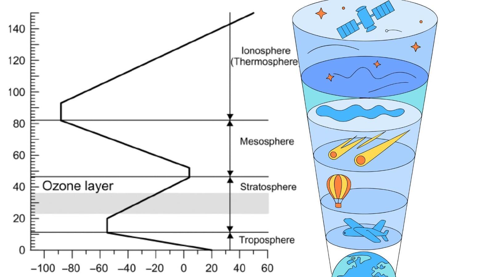
The table below lists the major layers of Earth's atmosphere with approximate altitude ranges and typical flying vehicles / systems that operate there. The diagram to the right (or below on narrow screens) shows a representative temperature profile versus altitude — note that the exact temperatures vary with time, latitude, and solar activity; this diagram gives the typical trend (decrease in the troposphere, increase in the stratosphere, decrease in the mesosphere, then strong increase in the thermosphere).
| Atmospheric Layer | Approx. Altitude Range (km) | Common Flying Vehicles / Systems |
|---|---|---|
| Troposphere | 0 – 12 | Commercial airliners, helicopters, general aviation, hot-air balloons, most drones, weather balloons (initial ascent) |
| Stratosphere | 12 – 50 | High-altitude UAVs (HALE), reconnaissance aircraft (e.g., U-2), stratospheric airships / long-endurance platforms, some high-altitude research flights |
| Mesosphere | 50 – 85 | Sounding rockets and sub-orbital probes; conventional aircraft cannot operate (air too thin) |
| Thermosphere | 85 – 600 | Low Earth Orbit (LEO) spacecraft during re-entry, International Space Station (~400 km). Many LEO satellites operate in/above this region. |
| Exosphere | 600 – 10,000 | High-Earth-Orbit satellites, transfer orbits, spacecraft traveling beyond Earth (trans-lunar, interplanetary) |
Note: the SVG shows a representative temperature trend — actual temperatures depend on latitude, local weather, and solar activity. The thermosphere's temperature rises strongly (but density is extremely low).
Atmospheric Layers — Altitude, Flying Vehicles & Temperature Profile
The table below lists the major layers of Earth's atmosphere with approximate altitude ranges and typical flying vehicles / systems that operate there. The diagram to the right (or below on narrow screens) shows a representative temperature profile versus altitude — note that the exact temperatures vary with time, latitude, and solar activity; this diagram gives the typical trend (decrease in the troposphere, increase in the stratosphere, decrease in the mesosphere, then strong increase in the thermosphere).
| Atmospheric Layer | Approx. Altitude Range (km) | Common Flying Vehicles / Systems |
|---|---|---|
| Troposphere | 0 – 12 | Commercial airliners, helicopters, general aviation, hot-air balloons, most drones, weather balloons (initial ascent) |
| Stratosphere | 12 – 50 | High-altitude UAVs (HALE), reconnaissance aircraft (e.g., U-2), stratospheric airships / long-endurance platforms, some high-altitude research flights |
| Mesosphere | 50 – 85 | Sounding rockets and sub-orbital probes; conventional aircraft cannot operate (air too thin) |
| Thermosphere | 85 – 600 | Low Earth Orbit (LEO) spacecraft during re-entry, International Space Station (~400 km). Many LEO satellites operate in/above this region. |
| Exosphere | 600 – 10,000 | High-Earth-Orbit satellites, transfer orbits, spacecraft traveling beyond Earth (trans-lunar, interplanetary) |
Note: the SVG shows a representative temperature trend — actual temperatures depend on latitude, local weather, and solar activity. The thermosphere's temperature rises strongly (but density is extremely low).
Layers of Atmosphere
Aircraft Cockpit (Boeing 737)
An aircraft cockpit is a specialized cockpit designed for flying an airplane.
It is located at the front of the aircraft and contains all flight, navigation, communication, and engine control systems.
An aircraft cockpit specifically contains flight instruments, navigation, and engine controls, while a fighter cockpit is more compact, combat-focused, and designed for high-G, high-speed operations.
Boeing 737 Cockpit
Cessna Cockpit
Airspeed Indicator
Altimeter
VSI
Heading Indicator
Turn Coordinator
Magnetic Compass
Primary Flight Display (PFD)
Airspeed Indicator (ASI): Measures the difference between pitot (dynamic) and static pressure to display indicated airspeed. Shows colored arcs for stall, normal, caution, and never-exceed speed ranges.
Altimeter: Uses static pressure acting on aneroid wafers to display altitude. Includes a Kollsman window for barometric pressure adjustment to ensure altitude accuracy.
Vertical Speed Indicator (VSI): Uses static pressure with a calibrated leak to show the rate of climb or descent. Displays both immediate trend and stabilized climb/descent rate.
Attitude Indicator: Shows pitch and bank by using a gyro fixed in a horizontal plane. Provides a stabilized horizon reference for instrument flight.
Heading Indicator (Directional Gyro): Provides stable heading information unaffected by magnetic disturbances. Must be aligned periodically with the magnetic compass.
Turn Coordinator: A canted gyro indicating roll rate and turn rate. Includes an inclinometer (ball) for slip and skid detection.
Magnetic Compass: Uses Earth's magnetic field to show heading. Serves as the primary reference for setting the heading indicator. Subject to magnetic dip, acceleration error, and turning errors.
Primary Flight Display (PFD): Combines airspeed tape, altitude tape, attitude indicator, heading indicator (HSI), VSI, slip/skid, and trend vectors in one modern digital screen.
Air Data Computer (ADC): Converts pitot-static pressures and temperature into digital airspeed, altitude, and VSI information.
Attitude and Heading Reference System (AHRS): Solid-state system providing attitude and heading without tumbling. Replaces vacuum gyros in modern aircraft.
| Instrument | Type | Data Source | Purpose | Typical Cockpit Location | Notes |
| Airspeed Indicator (ASI) | Pitot-static | Pitot + Static | Measures airspeed | Left of six-pack | Shows colored arcs for limitations |
| Altimeter | Pitot-static | Static | Measures altitude | Right of attitude indicator | Aneroid wafers & Kollsman window |
| Vertical Speed Indicator (VSI) | Pitot-static | Static (with calibrated leak) | Shows climb/descent rate | Lower right of six-pack | Shows trend + stabilized rate |
| Attitude Indicator (AI) | Gyroscopic | Vacuum / Electric | Shows pitch & bank | Center of top row | Critical for IMC |
| Heading Indicator (HI / DG) | Gyroscopic | Vacuum / Electric | Displays stable heading | Lower center | Requires compass alignment |
| Turn Coordinator (TC) | Gyroscopic | Electrical | Shows roll & turn rate | Lower left of six-pack | Includes inclinometer |
| Magnetic Compass | Magnetic | Earth’s magnetic field | Primary heading source | Top center of windscreen | Subject to magnetic error |
| PFD (Glass Cockpit) | Electronic | ADC + AHRS | Shows all primary flight data | Center display | Higher accuracy, no gyro tumbling |
The Airspeed Indicator (ASI) is one of the most essential primary flight instruments found in any aircraft cockpit.
The ASI measures Indicated Airspeed (IAS), which is subject to several types of errors such as instrument errors, position errors, and compressibility effects at higher speeds. However, IAS remains the primary reference for flight operations because it directly correlates with the aerodynamic forces acting on the aircraft. From IAS, a pilot or onboard systems can compute other types of airspeed: Calibrated Airspeed (CAS), which corrects for mechanical and installation errors; True Airspeed (TAS), which adjusts for air density changes with altitude and temperature; and Groundspeed (GS), which includes the effects of wind.
1. Anderson, John D., Jr. A History of Aerodynamics and Its Impact on Flying Machines, Cambridge University Press , New York