
Module 7
- Maintain equilibrium (balanced forces and moments)
- Be capable of controlled maneuvering
- Provide safe and manageable handling qualities
- Resultant forces = 0
- Resultant moments = 0
- A restoring force or moment must act to bring the aircraft back to equilibrium.
- Stability refers only to the initial response.
- Dynamic stability describes how motion evolves with time.
| Type | Description |
|---|---|
| Stable | Returns toward equilibrium |
| Unstable | Moves further away |
| Neutral | Stays in new position |
| Parameter | Static Stability | Dynamic Stability |
|---|---|---|
| Time Consideration | Immediate response | Time evolution |
| Focus | Initial tendency | Complete motion behavior |
| Mathematical Condition | Sign of stability derivative | Solution of differential equation |
| Can Oscillate? | Not considered | Yes |
| Can Grow With Time? | Not described | Yes |
Longitudinal static stability refers to the ability of an aircraft to develop a restoring pitching moment when its angle of attack is disturbed from the trim condition.
If an external disturbance increases the angle of attack, a statically stable aircraft produces a nose-down moment that returns it toward equilibrium. If the angle of attack decreases, the aircraft produces a nose-up moment restoring the original condition.
Mathematical condition for stability:
- The slope of pitching moment coefficient (Cm) vs angle of attack (α) must be negative
- dCm / dα < 0
Only when this restoring tendency exists is the aircraft considered longitudinally statically stable.
- Stable aircraft → negative slope
- Neutral aircraft → zero slope
- Unstable aircraft → positive slope
- Center of gravity (CG)
- Aerodynamic center (AC)
- Tail angle of attack depends on wing downwash.
- Tail moment arm strongly influences stability.
- Tail volume ratio determines effectiveness.
Elevator required for trim:
- CG is ahead of neutral point → stable
- CG equals neutral point → neutral stability
- CG behind neutral point → unstable
Typical aircraft static margin:
| Static Margin | Condition |
|---|---|
| SM > 0 | Stable |
| SM = 0 | Neutral |
| SM < 0 | Unstable |
Neutral Point (hNP)
Stick-fixed stability refers to the aircraft's stability when the elevator is held in a fixed position and is not free to move with the relative wind. In this state, the total pitching moment (Cm) is the sum of the moments generated by individual components like the wing, fuselage, nacelles, and powerplant.
Formula: Cm_total = Cm_{wing} + Cm_{fus} + Cm_{nac} + Cm_{tail} + Cm_{pwr}The wing aerodynamic center is the point where the pitching moment remains constant despite changes in lift
.- Stable Moment: Occurs when the center of gravity (c.g.) is ahead of the a.c.
- Unstable Moment: Occurs when the c.g. is aft of the a.c.
- Location: The a.c. is typically near 25% MAC, while the c.g. range spans 10-40% MAC.
- Cm: Total pitching moment coefficient.
- Cm0: Pitching moment at zero angle of attack (must be positive for trim).
- Cmα: Longitudinal static stability derivative (slope). For a stable aircraft, this value must be negative.
- α: Angle of attack.
| Component | Stability Effect |
|---|---|
| Fuselage | Generally unstable due to shape and wing airflow (upwash/downwash). |
| Tractor Powerplant | Generally destabilizing because of the force created by turning air at the propeller or intake. |
| Pusher Powerplant | Can reverse destabilizing effects and create stabilizing moments. |
The total pitching moment of the airplane is the summation of the moments generated by its individual parts:
- Wing: Typically provides an unstable (positive) slope when the C.G. is aft.
- Fuselage: Almost always destabilizing due to its shape and airflow interaction.
- Horizontal Tail: Provides a strong negative slope to pull the total sum into the Stable Region.
Note: For a stable aircraft, the "Total" line must have a negative slope (tilting downwards).
Aircraft longitudinal stability depends not only on the center of gravity (CG) and aerodynamic forces, but also on the behavior of control surfaces, especially the elevator.
Two important stability conditions are analyzed:
- Stick-Fixed Stability
- Stick-Free Stability
These conditions describe whether the control stick (elevator control) is held fixed or allowed to move freely.
In this condition:
- The control stick does not move
- The elevator deflection remains constant
- Aircraft response depends only on aerodynamic forces
Mathematical Stability Condition
If the derivative is negative:
- Increase in angle of attack produces a nose-down moment
- The aircraft returns to equilibrium
- The aircraft is statically stable
Center of Gravity
Forward CG increases stability, while aft CG reduces stability.
Tail Volume Ratio
| Parameter | Description |
|---|---|
| St | Tail Area |
| Lt | Tail Arm |
| S | Wing Area |
| c | Mean Aerodynamic Chord |
The elevator moves under aerodynamic hinge moments until equilibrium is reached.
Zero Hinge Moment Condition
When the elevator is free, it rotates until aerodynamic forces balance, causing the hinge moment to become zero.
When the elevator floats:
- The elevator deflects automatically
- The tail lift effectiveness reduces
- The restoring pitching moment decreases
Result: Stick-Free Stability < Stick-Fixed Stability
Stick Fixed Static Margin
Stick Free Static Margin
Since NP_free is forward of NP_fixed:
A stick force gradient is the change in yoke force as the aircraft’s airspeed deviates from trim condition. An aircraft’s yoke force gives pilots haptic feedback which improves their situational awareness without the need to assess instrument readings. A stick force gradient must provide a positive (pull) force when airspeed is lower than the trim airspeed and a negative (push) force when airspeed is higher than the trim speed. A stick force gradient that is zero provides no haptic feedback forces to the pilot at any airspeed regardless of trim. A positive slope stick force gradient creates an unstable aircraft.

.png)
X-axis: Airspeed
- Aerodynamic balancing is the control of hinge moment characteristics of aircraft control surfaces.
- The floating characteristics and stick force depend on hinge moment parameters.
- Two important parameters:
- Chα – Hinge moment variation with angle of attack.
- Chδ – Hinge moment variation with control surface deflection.
- Too low hinge moment → Controls become highly sensitive and unstable.
- Too high hinge moment → Controls become heavy and sluggish.
- Proper balancing ensures stability, controllability, and pilot comfort.
- To reduce excessive stick force.
- To avoid over-sensitive control response.
- To improve flight stability.
- To minimize pilot fatigue during long flights.
- To ensure safe and smooth aircraft operation at different speeds.
1. Set-Back Hinge Balance
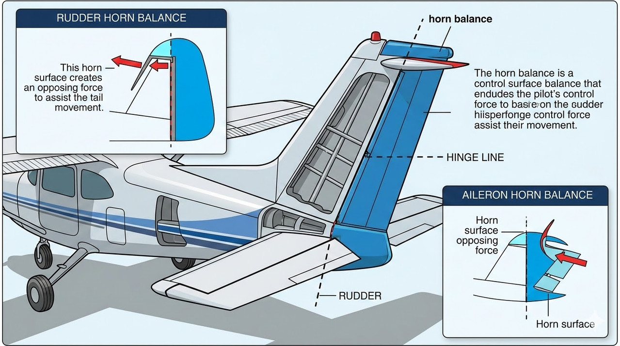
2. Horn Balance
3. Internal Balance
4. Beveled Trailing Edge
5. Tab (Balance / Trim / Servo Tab)
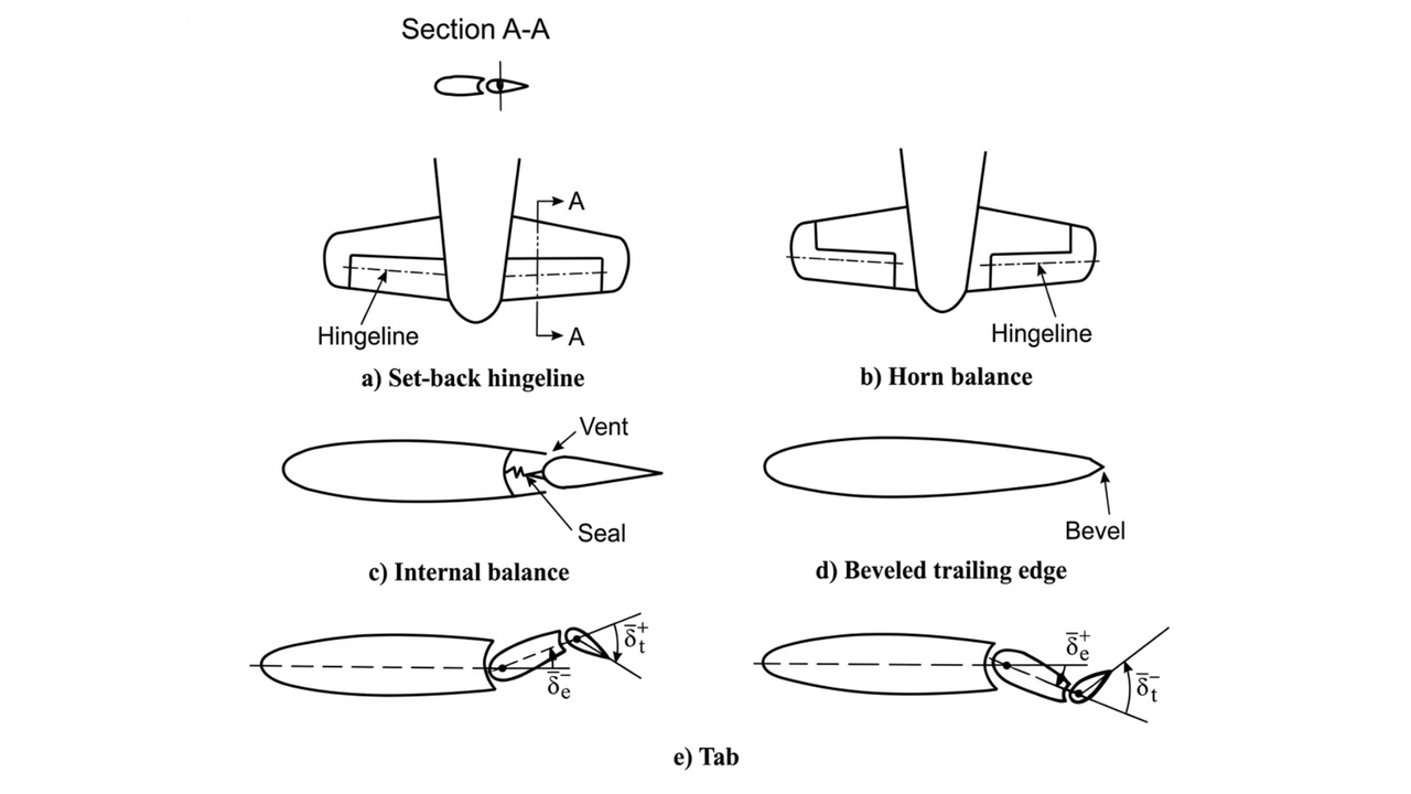
- Hinge line positioned slightly aft of the leading edge of control surface.
- A small portion of the surface lies ahead of the hinge line.
- Produces aerodynamic force that reduces hinge moment.
- Commonly used in light aircraft elevators and rudders.
- Examples: Cessna 172, Piper PA-28 Cherokee, Beechcraft Bonanza.
- Horn-shaped projection added ahead of hinge line.
- Usually located at the tip of rudder or elevator.
- Air pressure on horn produces counteracting hinge moment.
- Reduces pilot stick force.
- Examples: de Havilland Tiger Moth, Cessna 152, Piper J-3 Cub.
- Uses sealed internal chambers within control surface.
- Pressure difference generates balancing moment.
- Maintains clean aerodynamic profile.
- Suitable for high-speed and jet aircraft.
- Examples: Supermarine Spitfire, Hawker Hunter, MiG-21.
- Trailing edge cut at an angle.
- Alters pressure distribution over control surface.
- Provides minor hinge moment reduction.
- Simple and economical method.
- Examples: DHC-1 Chipmunk, Cessna 150, Piper PA-18 Super Cub.
- Small auxiliary surface attached to trailing edge.
- Produces balancing aerodynamic force.
- Types: Trim Tab, Servo Tab, Balance Tab.
- Highly effective for large control surfaces.
- Examples: Boeing 747, Airbus A320, Douglas DC-3.
- Reduces pilot effort and fatigue.
- Improves aircraft controllability.
- Enhances stability at high speeds.
- Prevents over-control and oscillations.
- Essential for safe and efficient aircraft operation.
| Method | Balancing Location | Effectiveness | Common Usage |
|---|---|---|---|
| Set-Back Hinge | Portion ahead of hinge | Moderate | Light aircraft |
| Horn Balance | External horn projection | Moderate to High | Trainers & small aircraft |
| Internal Balance | Inside control surface | High | High-speed jets |
| Beveled Trailing Edge | Trailing edge | Low to Moderate | Minor corrections |
| Tab | Auxiliary trailing surface | High | Large transport aircraft |
- Aileron reversal is an aeroelastic phenomenon occurring at high flight speeds.
- Aircraft wings are flexible due to aluminum and composite structures.
- Flexibility causes wing twisting under aerodynamic loads.
- This twist reduces or reverses the intended rolling effect of the aileron.
- It negatively affects aileron effectiveness and roll control.
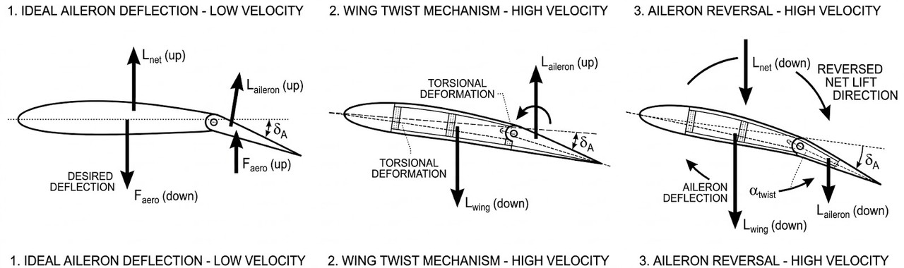
- Consider a right wing with a downward-deflected aileron.
- At subsonic speeds, aerodynamic load acts near mid-chord.
- At supersonic speeds, load shifts toward the rear of the wing.
- If the load centroid lies behind the elastic axis, the wing twists nose-down.
- This twist reduces the angle of attack of the wing section.
- Lift decreases instead of increasing as intended.
- In extreme cases, the lift direction reverses.
- The roll control derivative (ClδA) changes sign.
- This loss of effectiveness is called aileron reversal.
- Occurs mainly at high speeds.
- Limits the operational flight envelope.
- Requires careful structural and aerodynamic design.
- Wing stiffness plays a major role in preventing reversal.
- High-performance aircraft have a defined aileron reversal speed.
- The F-14 fighter aircraft experiences aileron reversal at high speed.
- Increase wing structural stiffness.
- Limit aileron deflection at high speeds.
- Use two sets of ailerons (inboard for high speed, outboard for low speed).
- Reduce aileron chord length.
- Use spoilers for roll control.
- Move ailerons toward the inboard wing section.
- The Boeing 747 uses three roll control devices: inboard ailerons, outboard ailerons, and spoilers.
- Outboard ailerons are disabled at high speeds.
- Spoilers (10–15% chord plates) create local lift loss for roll control.
- Proper wing stiffness ensures reversal does not occur within operational limits.