
Module 9
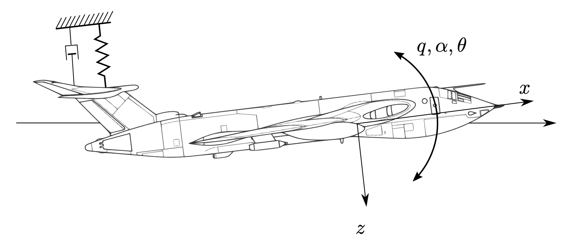
Euler’s equations describe the rotational motion of an aircraft about its center of gravity. They relate the aerodynamic moments to the angular velocities about the body axes.
\( I_x \dot{p} - (I_y - I_z)qr = L \)
\( I_y \dot{q} - (I_z - I_x)pr = M \)
\( I_z \dot{r} - (I_x - I_y)pq = N \)
Where:
- p – Roll rate
- q – Pitch rate
- r – Yaw rate
- L – Rolling moment
- M – Pitching moment
- N – Yawing moment
- Ix, Iy, Iz – Moments of inertia about body axes
Stability derivatives represent the change in aerodynamic forces and moments due to small changes in motion variables. They are obtained by linearizing the aerodynamic forces and moments about an equilibrium flight condition.
Examples of Stability Derivatives:
- \( C_{m\alpha} = \frac{\partial C_m}{\partial \alpha} \) → Pitch stability derivative
- \( C_{l\beta} = \frac{\partial C_l}{\partial \beta} \) → Lateral stability derivative
- \( C_{n\beta} = \frac{\partial C_n}{\partial \beta} \) → Directional stability derivative
- \( C_{lp} = \frac{\partial C_l}{\partial p} \) → Roll damping derivative
- \( C_{nr} = \frac{\partial C_n}{\partial r} \) → Yaw damping derivative
Using stability derivatives, aerodynamic moments can be expressed as:
\( L = \frac{1}{2} \rho V^2 S b (C_{l\beta}\beta + C_{lp}p + C_{lr}r) \)
\( M = \frac{1}{2} \rho V^2 S c (C_{m\alpha}\alpha + C_{mq}q) \)
\( N = \frac{1}{2} \rho V^2 S b (C_{n\beta}\beta + C_{np}p + C_{nr}r) \)
Equations of Motion
m u̇ = X
m ẇ = Z
Iy q̇ = M
Standard form of the characteristic equation:
The roots (eigenvalues) are defined as:
Where the damping components are:
| Damping Ratio ($\zeta$) | Type of Root | Time Response |
|---|---|---|
| $\zeta < -1$ | Two positive real roots | Exponentially growing motion |
| $0 > \zeta > -1$ | Complex roots (pos. real part) | Growing sinusoidal motion |
| $\zeta = 0$ | Complex roots (real part 0) | Undamped harmonic motion |
| $0 < \zeta< 1$ | Complex roots (neg. real part) | Underdamped decaying sinusoidal |
System Characteristics
Type of Root:Complex roots with a negative real part
Time Response:Decaying sinusoidal motion
Dynamic stability describes the time response of an aircraft after a disturbance. It determines whether oscillations decay, remain constant, or grow with time.
1. Short Period Mode
The short-period mode is an oscillation with a period of only a few seconds that is usually heavily damped by the existence of lifting surfaces far from the aircraft’s center of gravity, such as a horizontal tail or canard. The time to damp the amplitude to one-half of its value is usually on the order of 1 second.Motion: Rapid pitch oscillation involving angle of attack and pitch rate.
Equation:
ωn,sp = √(-Mα / Iy)
ζsp = -Mq / (2 √(-Mα Iy))
\( \ddot{\theta} + 2\zeta\omega_n \dot{\theta} + \omega_n^2 \theta = 0 \)
- High frequency oscillation
- Strongly damped
- Controlled mainly by horizontal tail
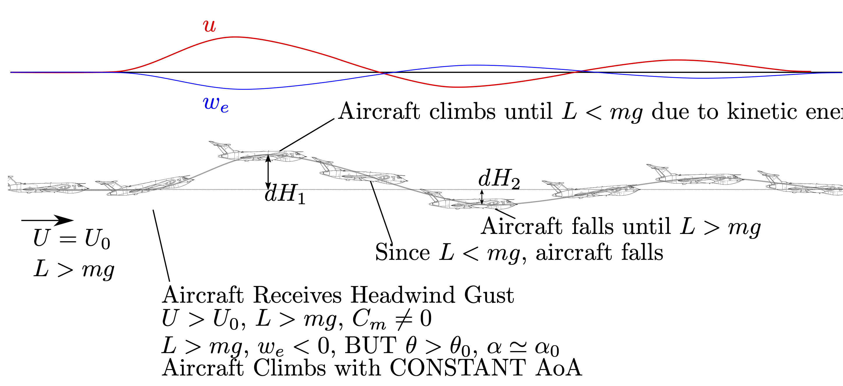
2. Phugoid Mode
Phugoid motion is a long-period, low-frequency longitudinal oscillation in aircraft characterized by alternating climbing and descending paths, where altitude and airspeed exchange periodically while pitch angle changes slightly. It is a stable, gentle motion caused by a disturbance in equilibrium, typically lasting 20–60 seconds, and is usually corrected automatically by the pilot or damped naturally.Motion: Long-period oscillation between altitude and velocity.
\( \ddot{h} + g \theta = 0 \)
- Slow oscillation
- Energy exchange between kinetic and potential energy
- Light damping
| Feature | Short Period Mode | Phugoid Mode |
|---|---|---|
| Duration / Period | Very short (seconds) | Long (minutes) |
| Damping | Usually heavily damped | Lightly damped |
| Airspeed (V) | Nearly constant | Varies significantly |
| Angle of Attack (α) | Varies significantly | Nearly constant |
| Primary Driver | Pitch stiffness and pitch damping | Exchange of potential and kinetic energy |
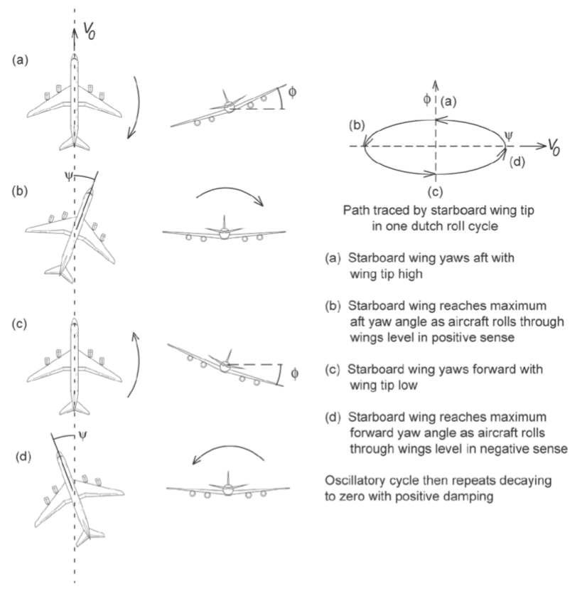
1. Dutch Roll Mode
A dutch roll is a combination of yawing and rolling motions. It can happen at any speed, developing from the use of the stick (i.e., aileron) and rudder, which generate a rolling action when in yaw. If a sideslip disturbance occurs, the aircraft yaws in one direction and, with strong roll stability, then rolls away in a countermotion. The aircraft “wags its tail” from side to side, so to speak. The term Dutch roll derives from the rhythmic motion of Dutch iceskaters swinging their arms and bodies from side to side as they skate over wide frozen areas.Motion: Coupled yaw and roll oscillation.
ωdr = √(-Nβ / Iz)
ζdr = -Nr / (2 √(-Nβ Iz))
\( \ddot{\beta} + C_{nr}\dot{\beta} + C_{n\beta}\beta = 0 \)
- Oscillatory yawing and rolling motion
- Controlled by vertical tail and dihedral effect
- Often damped using yaw damper
2. Spiral Mode
Motion: Slow divergence in bank angle.
(Clβ Cnr − Cnβ Clr) / Clp < 0
\( \dot{\phi} = C_{l\beta}\beta + C_{lp}p \)
- Very slow instability
- Aircraft gradually enters spiral dive
Directional Divergence
This results from directional (i.e, yaw) instability. The fuselage is a destabilizing body, and if an aircraft does not have a sufficiently large V-tail to provide stability, then sideslip increases accompanied by some roll, with the extent depending on the roll stability. The condition can continue until the aircraft is broadside to the relative wind.
Spiral Divergence
Spiral divergence or spiral instability is a condition where an aircraft is directionally very stable, but laterally very unstable. It is characterized by low angle of attack and high airspeed. When the lateral equilibrium of the aircraft is disturbed by a gust of air and a sideslip is introduced, the strong directional stability tends to yaw the nose into the resultant relative wind while the comparatively weak dihedral lags in restoring the lateral balance.
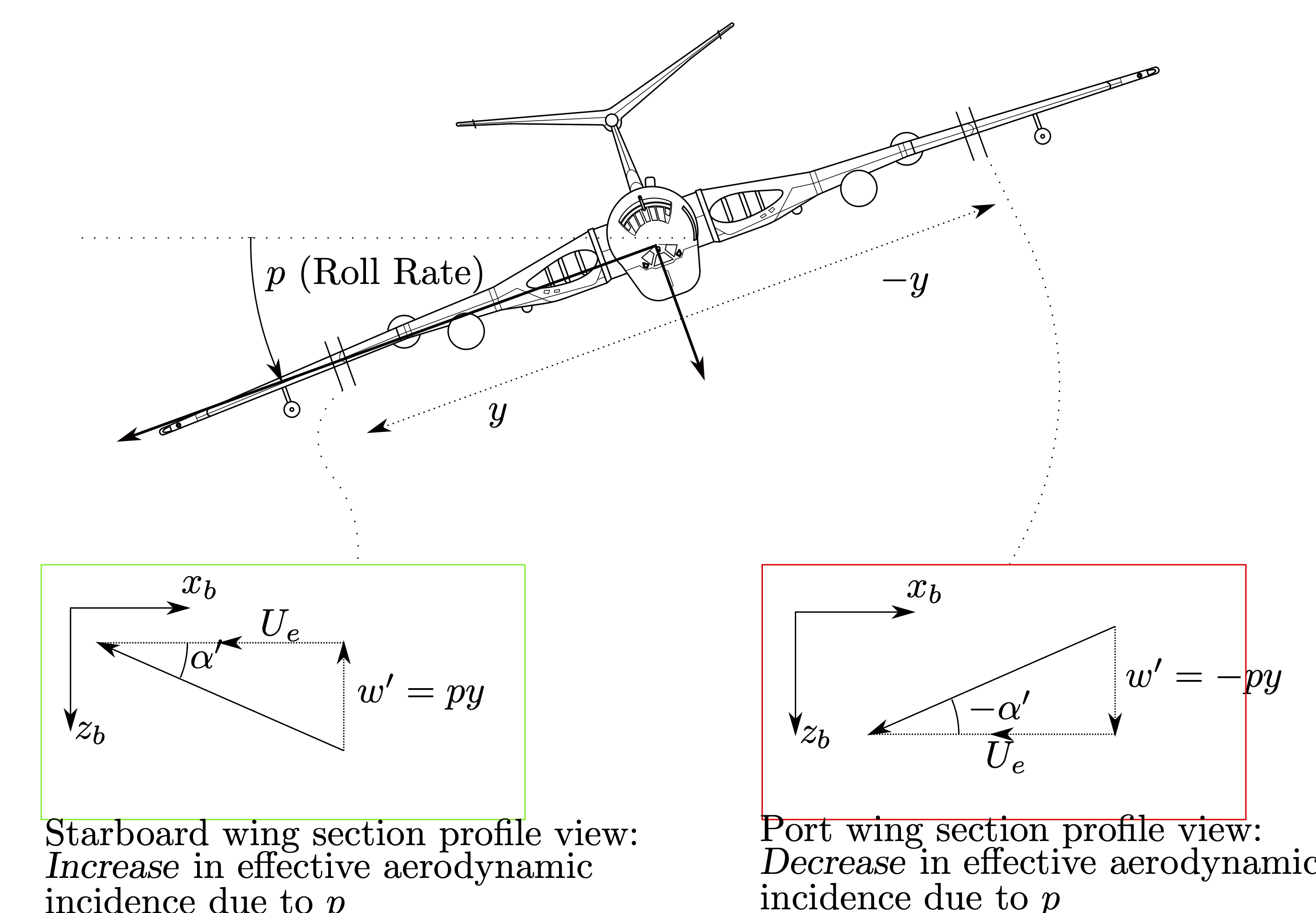
3. Roll Mode
Roll Subsidence:A pilot commands the roll rate by application of the aileron. Deflection of the ailerons generates a rolling moment, but the aircraft has a roll inertia and the roll rate builds up. Very quickly, a steady roll rate is achieved when the rolling moment generated by the ailerons is balanced by an equal and opposite moment proportional to the roll rate. When a pilot has achieved the desired bank angle, the ailerons are neutralized and the resisting rolling moment very rapidly damps out the roll rate. The damping effect of the wings is called roll subsidence.Motion: Pure roll damping motion.
τroll = − Ix / Lp
\( \dot{p} = C_{lp}p \)
- Highly damped
- Aircraft quickly stops rolling after disturbance
| Stability Mode | Type of Motion | Axis of Motion | Speed of Response | Main Characteristics |
|---|---|---|---|---|
| Short Period Mode | Pitch oscillation | Longitudinal axis | Fast | Rapid change in angle of attack and pitch rate, strongly damped |
| Phugoid Mode | Altitude and velocity oscillation | Longitudinal axis | Slow | Exchange between kinetic and potential energy, lightly damped |
| Dutch Roll Mode | Yaw and roll oscillation | Lateral–Directional | Moderate | Oscillatory yawing and rolling motion, common in swept-wing aircraft |
| Spiral Mode | Gradual bank divergence | Lateral–Directional | Very slow | Aircraft slowly enters spiral dive if not corrected |
| Roll Mode | Pure rolling motion | Lateral axis | Very fast | Strong roll damping due to wings |
The state-space matrix ẋ = Ax for the UAV is defined as:
The characteristic equation is found via $|\lambda\mathbf{I} - \mathbf{A}| = 0$:
Phugoid (Long Period)
Eigenvalues:
$\lambda_{1,2} = -0.0171 \pm i(0.213)$
Time to half amp ($t_{1/2}$):
$40.3 \text{ s}$
Period: $29.5 \text{ s}$
Cycles ($N_{1/2}$): $1.37$
Short Period
Eigenvalues:
$\lambda_{3,4} = -2.5 \pm i(2.59)$
Time to half amp ($t_{1/2}$):
$0.28 \text{ s}$
Period: $2.42 \text{ s}$
Cycles ($N_{1/2}$): $0.11$
The lateral-directional linearized equations of motion in state-space form ($\dot{\mathbf{x}} = \mathbf{Ax} + \mathbf{Bu}$) are expressed as:
Where:
$\beta$: Sideslip angle | $p, r$: Roll and Yaw rates | $\phi$: Roll angle | $\delta_a, \delta_r$: Aileron and Rudder deflections
If we consider the Dutch roll mode to consist primarily of sideslipping and yawing motions, then we can neglect the rolling moment equation. With these assumptions, the system reduces to:
Solving for the characteristic equation yields:
From this expression, we can determine the undamped natural frequency and the damping ratio as follows:
The characteristic root for this equation is defined as:
The stability derivatives $L_{\beta}$ (dihedral effect) and $N_{r}$ (yaw rate damping) usually are negative quantities. On the other hand, $N_{\beta}$ (directional stability) and $L_{r}$ (roll moment due to yaw rate) generally are positive quantities.
or
Increasing the dihedral effect $L_{\beta}$ or the yaw damping $N_{r}$ (or both) can make the spiral mode stable.
Damping Ratio ζ = -Mq / (2√(Mw × Zw))
Period of oscillation T = 2π / ωₙ
The state-space matrix for longitudinal motion is defined as:
Characteristic Equation: $\lambda^4 + 5.05\lambda^3 + 13.2\lambda^2 + 0.67\lambda + 0.59 = 0$
Phugoid Mode
$\lambda_{1,2} = -0.0171 \pm i(0.213)$$t_{1/2} = 40.3 \text{ s}$
$P = 29.5 \text{ s}$
$N_{1/2} = 1.37 \text{ cycles}$
Short Period Mode
$\lambda_{3,4} = -2.5 \pm i(2.59)$$t_{1/2} = 0.28 \text{ s}$
$P = 2.42 \text{ s}$
$N_{1/2} = 0.11 \text{ cycles}$
Numerical State-Space Matrix for Lateral Motion:
The resulting characteristic equation is:
$$ \lambda^4 + 9.417\lambda^3 + 13.982\lambda^2 + 48.102\lambda + 0.4205 = 0 $$Lateral Eigenvalues (Exact):
- Spiral Mode: $\lambda = -0.00877$
- Roll Mode: $\lambda = -8.435$
- Dutch Roll: $\lambda = -0.487 \pm i(2.335)$
Approximate Modal Results:
1. Spiral Mode:
$$ \lambda_{\text{spiral}} = \frac{L_{\beta}N_{r} - L_{r}N_{\beta}}{L_{\beta}} $$ $$ \lambda_{\text{spiral}} = \frac{(-16.02 \text{ s}^{-2})(-0.76 \text{ s}^{-1}) - (2.19 \text{ s}^{-1})(4.49 \text{ s}^{-2})}{-16.02 \text{ s}^{-2}} $$ $$ \lambda_{\text{spiral}} = -0.144 \text{ s}^{-1} $$2. Roll Mode:
$$ \lambda_{\text{roll}} = L_{p} = -8.4 \text{ s}^{-1} $$3. Dutch Roll Mode:
The roots are determined from the characteristic equation:
$$ \lambda^2 - \left( \frac{Y_{\beta} + u_0 N_{r}}{u_0} \right) \lambda + \frac{Y_{\beta} N_{r} - N_{\beta} Y_{r} + u_0 N_{\beta}}{u_0} = 0 $$ $$ \text{or } \lambda^2 + 1.102\lambda + 4.71 = 0 $$Which yields the following roots and parameters:
$$ \lambda_{\text{DR}} = -0.51 \pm 2.109i $$ $$ \omega_{n_{\text{DR}}} = 2.17 \text{ rad/s} $$ $$ \zeta_{\text{DR}} = 0.254 $$