Aircraft Performance

Module 6

6.1 Take-off
6.2 Rate of Climb
6.3 Turning flight
6.4 Gliding flight
6.5 Landing
6.6 V-n diagram
6.1 Take-off
Takeoff Phase
Takeoff Phase
Takeoff is the phase of flight in which an aircraft accelerates along the runway, generates sufficient lift, and transitions from ground roll to airborne flight.Takeoff is the process of becoming airborne from the ground by increasing speed until the wings produce enough lift to overcome the aircraft’s weight.

Takeoff occurs when: Lift ≥ Weight and sufficient thrust overcomes drag and rolling resistance.

Four Phases of Take-off
Takeoff progresses from acceleration → nose rotation → airborne transition → stabilized climb. Ground Roll (Takeoff Roll): Aircraft accelerates along the runway. Thrust overcomes rolling resistance and drag. Lift gradually increases as speed builds. Rotation: At rotation speed (VR), the pilot gently raises the nose. Angle of attack increases. Lift increases rapidly. Liftoff: Aircraft leaves the runway surface. Lift becomes equal to or slightly greater than weight. Aircraft becomes airborne. Initial Climb: Aircraft establishes a positive rate of climb. Landing gear is retracted (if applicable). Aircraft accelerates to climb speed (VX or VY).
Takeoff factors
The important factors of takeoff or landing performance are: • The takeoff or landing speed is generally a function of the stall speed or minimum flying speed. • The rate of acceleration/deceleration during the takeoff or landing roll. The speed (acceleration and deceleration) experienced by any object varies directly with the imbalance of force and inversely with the mass of the object. An airplane on the runway moving at 75 knots has four times the energy it has traveling at 37 knots. Thus, an airplane requires four times as much distance to stop as required at half the speed. • The takeoff or landing roll distance is a function of both acceleration/deceleration and speed.
6.2 Rate of Climb
Climb Performance
Climb Performance
Positive climb performance occurs when an aircraft gains PE by increasing altitude. Two basic factors, or a combination of the two factors, contribute to positive climb performance in most aircraft: 1. The aircraft climbs (gains PE) using excess power above that required to maintain level flight, or 2. The aircraft climbs by converting airspeed (KE) to altitude (PE).

Rate of climb (RoC) is the vertical speed of an aircraft, commonly measured in feet per minute (fpm), representing the rate of altitude gain. It is driven by excess power—the difference between power available and power required—and is heavily influenced by weight, density altitude, and aerodynamic drag.

Best Rate of Climb for jet and propeller aircraft

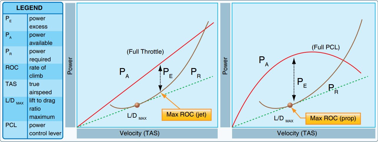
Best Rate of Climb comparison for jet and propeller aircraft. Source: FAA Pilot Handbook

Factors Affecting Rate of Climb

Altitude: Rate of climb decreases as altitude increases due to lower air density reducing engine thrust.

Weight: Higher gross weight decreases rate of climb and requires a lower.

Temperature: Higher temperatures decrease air density, reducing engine power and propeller efficiency, resulting in a lower RoC.

Aerodynamics: Lower drag (clean configuration) increases RoC.

Angle of Climb (AOC)

Angle of Climb (AOC) is the angle between the aircraft’s flight path and the horizontal ground.

It represents how much altitude is gained compared to horizontal distance traveled.

Angle of Climb measures steepness of ascent, and maximum AOC is achieved when the aircraft has maximum excess thrust, allowing it to clear obstacles efficiently.

To achieve Maximum Angle of Climb (VX), by flying at VX (best angle-of-climb speed) and provides maximum altitude gain in the shortest horizontal distance.

What Determines AOC?

AOC depends on excess thrust available.

Excess thrust = Thrust available − Thrust required.

The greater the excess thrust, the steeper the climb angle.

Jet aircraft:Maximum AOC occurs near the speed where thrust required is minimum (around L/D max).

Propeller aircraft:Maximum AOC usually occurs below L/D max speed, often just above stall speed.

6.3 Turning flight

Coming soon

6.4 Gliding flight
Jet Aircraft Performance: Range & Endurance
Specific Fuel Consumption
In the case of jet powered aircraft, specific fuel consumption is given as Thrust Specific Fuel Consumption (TSFC). It is defined as the weight of fuel consumed per unit thrust per unit time. Here, thrust is used in contrast to power, which is typical for propeller-driven aircraft. The relationship between fuel consumption and thrust available (TA) is expressed as:
N(fuel) / s = (TSFC) TA
Maximum Endurance
For level, un-accelerated flight, the pilot adjusts the throttle such that thrust available (TA) equals the thrust required (TR). Therefore, the weight of fuel consumed per hour will be minimum when thrust required is minimum. For minimum thrust required, the ratio CL / CD should be maximum. Maximum endurance occurs when the airplane is flying at a velocity such that TR is minimum. Endurance is derived by considering the rate of fuel weight change over time. The weight of fuel consumed per unit time is proportional to the thrust available and the specific fuel consumption coefficient (ct):
dW = -ct TA dt
Rearranging to solve for the time increment (dt):
dt = -dW / (ct TA)
For steady, level flight, the pilot maintains TA = TR. Substituting TA = W / (CL/CD):
dt = (1 / ct) (CL / CD) (dW / W)
Integrating from the initial weight (Wo) to the final weight (W1) gives the overall endurance:
E = (1 / ct) (CL / CD) ln(Wo / W1)
Maximum endurance is achieved when the aircraft flies at a velocity where the thrust required is minimum. The overall endurance (E) is computed as:
E = (1 / ct) (CL / CD) ln(W0 / W1)
Maximum Range
Range is the integral of the distance covered (ds) over the change in aircraft weight. To obtain the expression for range, the aircraft must consume the minimum weight of fuel per unit distance. For a jet aircraft, minimum fuel per unit distance corresponds to a minimum TA / V ratio. Since TA = TR in steady flight, range is maximum when TR / V is minimum. This corresponds to the tangent point on the thrust required curve. The distance increment is defined as:
ds = V dt = -V dW / (ct TA)
In steady level flight, TA = D and L = W. Substituting these into the range equation:
R = ∫ (V / ct) (CL / CD) (dW / W)
For a jet aircraft, maximum range is achieved when flying at a velocity such that CL1/2 / CD is maximized, which corresponds to CL = (3CDo / K)1/2. Maximum range occurs when CL1/2 / CD is maximum. The requirement for this corresponds to:
CL = (3CDo / K)1/2
Evaluating the integral from W1 to Wo yields the final range expression:
R = 2 (2 / (ρ S))1/2 (1 / ct) (CL1/2 / CD) (Wo1/2 - W11/2)
Mathematical Derivations: Propeller Performance
Derivation of Endurance (E)
For a propeller aircraft, endurance is the total time spent in the air. We begin with the relationship where the change in fuel weight (dW) is proportional to the engine power (P), the specific fuel consumption (c), and the time increment (dt):
dW = -c P dt   ⇒   dt = -dW / (c P)
The engine power (P) is related to the power required (PR) and propeller efficiency (η) by P = PR / η. Since PR = D V, we substitute:
dt = -(η / c) (1 / (D V)) dW
Using steady level flight conditions (L = W) and substituting Velocity V = (2W / (ρ S CL))1/2 and Drag D = W (CD / CL):
dt = (η / c) (CL3/2 / CD) (ρ S / 2)1/2 (W-3/2) dW
Integrating from W1 to Wo yields the maximum endurance formula:
E = (η / c) (CL3/2 / CD) (2 ρ S)1/2 (W1-1/2 - Wo-1/2)
Endurance is maximized when the aircraft flies at a velocity where CL3/2 / CD is maximum.
Derivation of Range (R)
Range is the total distance covered on a full tank of fuel. The distance increment (ds) is defined as velocity (V) multiplied by the time increment (dt):
ds = V dt = -V dW / (c P)
Substituting the propeller engine power relationship P = D V / η:
ds = -V dW / (c (D V / η)) = -(η / c) (1 / D) dW
By multiplying by (W / W) and noting that for steady level flight L = W, we get:
ds = (η / c) (L / D) (dW / W) = (η / c) (CL / CD) (dW / W)
Integrating from the final weight (W1) to the initial weight (Wo) results in the Breguet Range Equation for propeller aircraft:
R = (η / c) (CL / CD) ln(Wo / W1)
This derivation shows that maximum range for a propeller-driven aircraft occurs when the aircraft is flying at a velocity where the lift-to-drag ratio (CL / CD) is maximum.
6.5 Landing
6.6 V-n diagram

Coming soon

Aircraft Performance by Dr Aishwarya Dhara
Back
Share -